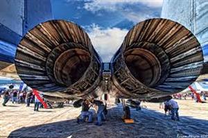
F-15 Engine
Early F-15A/Bs used two Pratt & Whitney F1OO-PW-100 turbofans, each rated at 23,830 pounds thrust with afterburner. Since all accessories (generators, etc.) are mounted in the AMAD, the left and right engines of the F-15 are interchangeable, simplifying maintenance considerably.
The F100 is a two-shaft turbofan with a high-augmentation afterburner. The engine is equipped with a direct pitot-type titanium Intake with a fixed nose bullet. There are 21 inlet guide vanes in a single row equipped with variable-camber trailing edges.
The fan has three stages and the fan blades and discs are of titanium construction. The compressor is a 10-stage axial design constructed primarily of titanium, Inconel and other high-temperature alloys. The first three stages of the compressor are equipped with variable stator blades to allow optimum airflow scheduling.
The afterburner has five concentric spray rings in flow from the core engine, and two slightly further downstream in the fan bypass airflow. The flameholder assembly is downstream of the spray rings, and is connected with a high-energy ignition system that permits a modulated light-up. The outer bypass duct and other major afterburner assemblies are fabricated In sheet and stringer titanium, while the interior liner is of coated Haynes-188. A small augmentor fuel drain is located on the bottom of the fuselage beneath each engine to ensure that fuel to does not accumulate In the afterburner. Originally this drain protruded downward a couple of inches beneath the fuselage, but its location continued to injure ground crews, so by the mid-1990s most aircraft had the protrusion removed and the drain is now flush with the surrounding fuselage All early F100 variants are 191.2 inches long, 46.5 inches in diameter, and weigh 3,033 pounds.
Later, the Improved Performance Engine (IPE) program produced engines from each manufacturer that have an increase to approximately 29,000 pounds sea-level static thrust. These engines, the F100-PW.229 and F110-GE-129 have been successfully demonstrated in an F-16C and a modified F-15A. Both engines are available to power the F-16C/D and F-15E.
 Air is fed to the engines by two straight two- dimensional external compression Inlets, one on each side of the fuselage. Air inlet controllers are provided by Hamilton Standard, with actuators by National Water Lift, The inlets are identical, but completely separate, and are capable of operating asymmetrically. Each system consists of three variable ramps, a variable diffuser ramp and a variable bypass door. The entire Intake rotates about a pivot on the lower cowl lip to provide optimum airflow at all angles of attack. The upper leading edge can rotate up to 11* below and 4* above the horizontal. The variable ramps provide air at optimum subsonic flow to the face of the engine throughout the aircraft speed range.
A series of tests in the Air Force Arnold Engineering Development Center wind tunnel has established that the inlet is essentially stall-free at any flight attitude and all altitudes. The inlets also provide a small measure of lift, and serve to unload the horizontal stabilizer, much the same as a canard, allowing a smaller stabilator. Most F-15S have received various doubler panels (some of them very large) on the side of their Intakes to correct various stress cracks.

Comments are closed, but trackbacks and pingbacks are open.